Tuesday, March 29, 2011

Bill Spurling & Linotype.org

Brian Donnell seated. Bill Spurling standing.
At Bill Spurling’s Place. 
Bill Spurling is a great resource for linotype operators and enthusiasts in this region and beyond. He and his son Tristan have managed to save many machines from the scrap yard including these:

1912 Model 5, 1922 Model 8, 1923 Model 8, 1924 Model 14, 1938 Model 29, 1946 Model 31, 1949 Model 31, 1949 Model 30, 1962 Model 30, 1960 Model 29

Many of the above listed machines have been stripped down and rebuilt by Bill, so it’s been great to pick his brain while learning tricks and general maintenance on our 31. He has been generous with his time and spare parts when needed. Also, one of his 31s is a cousin of our machine. It shipped in the same year and is only 302 machines younger than ours, so it has been helpful to study a nice clean runner for comparison.

Bill is the man behind the website Linotype.org which is full of useful information including a chart of machine serial numbers, downloadable .pdf manuals, regional linotype history, etc. From his site: “This site is dedicated to the unsung heros that made it all work, the Linotype Machinists and Machinist-Operators everywhere, past, present and future.” Hear, hear.

Monday, March 28, 2011

Brian Donnell

Brian Donnell operating a 6 pocket, “2 in 1” Linotype 31
at Advanced Letterpress in Portland, Oregon
Brian Donnell has bailed me out on several occasions when I’ve found myself in over my head with linotype issues. When he doesn’t have the answer, he will offer what I like to call a “Donnellism,” which is a story or a bit of wisdom that somehow relates to the problem. This tidbit always leads me to finding a solution to the problem, even if it hits me hours later. Brian is a good teacher that way. As a journeyman printer, Brian is one of the young “old guys” who in 1974 got his start at the end of an era that was at the height of printing craftsmanship. Brian is generous in sharing his knowledge, and has created an excellent on-line primer for letterpress printing. Check it out here. Also, Brian can be found on Briar Press here. 

Wednesday, March 16, 2011

Replace Keyboard Rubber

Many of the keys had a very slow response, or no response at all which is often due to old glazed & hardened rubber. The idea is that the surface of the hardened rubber doesn't provide enough friction for the cam to rotate, so it wobbles and skids along the surface until it catches. Also, it is not uncommon for the key cams to be over oiled causing oil to drip onto the surface of the rubber roller and breaking it down prematurely.

Bill Spurling mentioned that he has seen rollers that appear almost as if they have been sliced by the cams. The roller I was mostly concerned about wasn't that bad, but it was glazed quite a bit, and it did have some pretty good grooves worn into the surface.

As you can see from the photo below, oil also creeps in through the oil points at the ends of the frame. Good thing to remember to not over oil these.

Here you can see that the rubber has broken down and filled the space in between the teeth creating a smooth surface across the cam.
I've heard that replacing the rubber can be a bit of a challenge. It's pretty tricky to slide the thick walled rubber roll onto the steel core. Apparently there is a tool for this job, and apparently folks like Dave Seat make this process look as easy as the book describes. The book will describe the steps: “slide the rubber on while holding your thumb over the end. This will cause the air inside to be compressed and cause the roll to expand and slip easily upon the shaft.” Really? Sounds like a snap. But, honestly, I knew I was looking at a project. Brian Donnell had also told me that he had spent a lot of time fighting with the keyboard rubber years ago when it was necessary to replace his.

I tried to apply a bit of rubber rejuvenator, a product that we keep around the shop for use when the offset dampening rollers become glazed. It did seem to bring back a bit of life to the rubber. The surface of the rubber roll had a little less sheen. But after studying the caked cam teeth once more, and perhaps because I can be a bit of a glutton for punishment, I decided to replace the rubber.


No turning back now. Of course the books say: “slip the old rubber off” or something like that. There was no slipping. The rubber roll liked the steel core and wasn't planning on going anywhere. The book the mentions: “it may be necessary to slit the rubber length wise to remove it.” Yup.
After removing the old rubber roll, I inspected the core. It was a bit like inspecting the growth rings on a tree stump. I could count at least 5 faint knife score lines produced by the hands of operators and mechanics from the past. A bit humbling. It was kind of cool to be the 6th score line on the core.
Now the fun. Apparently by swiftly whacking this rubber roll on to the core, the seal of one’s palm will be enough to push air through, expanding the almost 1/4 inch thick rubber roll easily into place. I managed to get about 1/16th of the way on. I struggled with this for about 30 minutes. I found a tapered steel “plug” to place on the open end, and by pulling and pounding with a mallet, managed to move it on another 1/2 inch.
I decided to employ a second method: “If no special tool is available, the roll may be put on easily by starting one end on the shaft and filling the roll with water. Hold the hand over the top and press down allowing the water to escape as the roll goes into place” I tried this method for another 30 minutes with a little more success. The roll was now 1/3 of the way in place. It was a tiring process. My hands were throbbing and I now had water covering the front of my shirt and pants. Picture this: middle aged man rolling around on the floor with a steel rod and rubber roll, red in the face, cursing and grunting, splashing water over himself. What I didn't realize was that our normally quiet after hours industrial warehouse district was in fact swarming with kids going to a neighboring rave. So what I thought was an empty pitch black quiet side street outside our oversized shop windows was actually filled with young party goers who were probably enjoying the spectacle. Ha! Anyway it was around this time when the magical sweet spot happened. Somewhere around the halfway point, the roll gained momentum, and with a sloppy “swack” it slid into place.

My heart sunk a bit when I discovered this. What?!? The roll is too short? Crap! I didn't measure the roll before I spent the last hour and half fighting with it to go on. After a bit of kneading to rubber into place, the roll expanded. Of course! I just spent all of that time putting pressure on it, no wonder it would compress. Whew.
Here it is, as it should look.
Ready to be placed back into the key cam frame.


Reassembling the frame.


Completed frame, and tired dude.

Sunday, March 13, 2011

Clean and Oil Key Cams

Getting at the keyboard. 1st step: remove the cam yoke frames. They are easy to get to, and cleaning and oiling the key cams is fairly routine maintenance. In fact, the Linotype books will tell to you to clean and oil the cams twice a year.
Here is the keyboard swung open with the front and back cam yoke frames removed. Be careful before swinging the keyboard, make sure there are no key reeds engaged. More on that later.
Here's the rear cam yoke frame before cleaning.
Beginning to remove key cams. It's important to keep these cams in order. Due to position and frequency of use, the key cams will wear slightly differently than others. 
One tip to cleaning the cams is to thread each one onto a wire. This way they will stay in order, and you can soak all of them at once. Thanks to Bill Spurling for that one. 
I like this photo. This is the rear set of cams (indicated by different color wire) Looks like some kind of spinal column. Yes, it is the spinal column of language, the printed word, modern civilization...  the backbone of the "art preservative of all other arts..." wooo.  Believe me, after cleaning 90 keys over an open tub of white gas, you'll be allowing your mind to flutter off to these fun thoughts as well.
Pictured in the foreground are both cam yoke frames. The cams for the front frame are soaking in white gas. The rubber roller has been removed. At this point I'm debating on replacing the rubber. More on that later, too.
While the keys are soaking and your head is off in la la land, the frames themselves can be cleaned. Here's evidence off gummed up and slow responding triggers.
Testing to see that the triggers move freely. Once this is done, this is when it is necessary to "lock" the triggers into place by inserting a 1/16" wire the length of the frame as the books will describe.
Oooh, look at the teeth on this cam. Problems. This is a good example of why these need to be cleaned. Unfortunately, I didn't count the position of this cam to see if my notes confirmed that this cam corresponded with a key that showed slow response or no response, but you can bet that would be the case. The rubber may have broken down in this position due to oil on the roller. These cams need to be oiled, but only the slightest amount. Clock oil won't gum, but it does run. It's amazing that the tiniest drop will spread a good amount after working the cam a bit. After reinstalling the cams, I let the frames sit over night before returning them to the keyboard so I could remove any remaining extra oil that may have dripped onto the rubber.
Cams clean and scrubbed with brass wire hand brush. Waiting in order to be oiled. 
Whoops. A bit too much oil here. My standard procedure was to spin the cam for 20 to 30 seconds until it spins freely. This is something that I got a feel for fairly quickly. Also, each cam really did seem to have slightly different action and feel. Very subtle, but it was noticeable. Often it was the sound of the cam spinning that gave the cam individual feel. Imagine the difference in sound of a june bug vs. a small dragonfly flying past your ear. Something like that. Woo. Maybe the white gas talking again, but it was interesting. The different feel of the cams was due in part to wear, but also it was evidence that this thing was built by a human. Pretty cool. 


After the cam is cleaned & oiled, the teeth can be dressed if need be. For the most part, this didn't seem to be necessary. I did attempt to file a couple, but didn't have the correct tool. I tried to use a tiny file used for cleaning automotive ignition points, but it was still a bit too thick. One swipe made a mess of the teeth, so I decided not to butcher any addition ones.
I read that most keyboards contained a space band key cam that was slightly larger than the rest. When I pulled the cams from the frame, I hadn't noticed. After cleaning and oiling 90 cams, it stood out. It's a bit like spotting the queen bee in a full hive of worker bees. Well, kind of. But I think this is easier. I still can't spot that queen bee. Anyway, the space band cam is on the left.
I like this photo, too. Here the cam is resting on the trigger, ready to drop onto the rubber roller (which is still removed allowing for the photo to be taken from this perspective)
Here are the cleaned and oiled cams back in place.  

Saturday, March 12, 2011

Starting on Keyboard work

Back to the Keyboard. Where to start? There are stuck keys, keys with no response, doubles... a lot to learn! I decided to make copies of the keyboard diagram and make notes.

Hopefully I'd discover a pattern that would allow me to focus on a particular area: key levers, key bars, cams, key reeds, escapements and magazines. If I couldn't decipher a pattern, I would at least get a better idea of the positioning and relationship of keys to key reeds, and which rows / key levers activated key cams on the front cam frame or the back frame. It was a fun exercise.

Unfortunately it revealed that there were a lot of problems and that there wasn't exactly a pattern. I did decide that a majority of keys that triggered the front key cams had problems, mainly slow response. Probably due to worn or glazed rubber. But there were also classic examples of sticking key bars (multiple mats dropping), etc. I was looking forward getting started. Keyboard work seemed to be methodical and slow going. There are a lot of small parts which have to be kept in order. It was the kind of work that offered a meditative order that was welcomed after long days of computer pre-press, printing and working to meet customers' often tight deadlines.

Cleaning Well & Plunger

Cleaning the well.

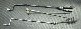
Here are some tools for the job. 
Its been suggested that it may not be the best idea to use the tool pictured on the bottom, as there is a chance that the wire that makes up the brush could break off and plug up holes at the mouthpiece. Certainly seems plausible. The tool on the top worked nicely.


Cleaning the plunger. Bill brought this device. I'm sure most folks don't have access to one of these. I'd be interested in hearing other folks' routine / technique in cleaning the plunger. From a safety standpoint cleaning the plunger is where exposure to potential dangerous oxide seems to be the greatest.  

Before re-seating the plunger in the well, we placed it in the pot to bring it up to temperature for several minutes.  

Fluxing the metal. Takes just a couple small flakes to do the job. 


Thursday, March 10, 2011

Stuck Pump Plunger

One of the first things that would require some attention on this machine was that the pump plunger did not want to be removed for routine cleaning. Using some beefy channel lock pliers, we tried to pull while slowly twisting. As some books suggested, we also attempted tapping gently on the end of the plunger and then gave it another go. It wasn’t budging. However, at this point it wasn’t entirely stuck. The machine was producing slugs.

Back end of machine with view of plunger and pot.
Also, notice quick drop is released

So we ignored it for the time being. The keyboard was barely functioning so I figured I’d focus on coming up with a keyboard repair plan first. I wasn’t so lucky. The next work session made it impossible for me to ignore the plunger, since it only took 5 or so more lines before the plunger became really stuck, it would no longer return to neutral position and was stuck almost at the bottom of its stroke. Fortunately, the plunger rod had popped free from the pump lever via the safety spring on the plunger rod, and the machine was not bound up. It was time to come up with a new plan for plunger extraction.

Most information that I came across regarding extracting a stuck plunger pump suggested ladling the metal out until the top of the plunger was exposed. The information then suggested to place oil or tallow in the well above the plunger and allow it to soak in for a few minutes before attempting to repeat tapping and pulling at the plunger rod with a monkey wrench. Ladling metal out of the pot at this point didn't appeal to me. I decided to explore other options before going that route.

Brian Donnell  offered some additional suggestions that sounded a bit more promising:
  1. Run a rod thru the upper hole and tap upwards on it with a hammer.
  2. Make a loop of several strands of wire thru the top hole and use a crowbar thru the loop and against the frame.
  3. Maybe don't use a wrench above the pin hole on the plunger shaft, only below the pin hole, since the rod is weak at that point.

I liked number 2.  Using leverage to get at a problem seemed to be a smarter way to work rather than throwing a hammer at it. At least it seemed like a good starting point. 

With option number 2 being on the top of my list, I was still hesitant to put a lot of force on this thing. Since I hadn’t done this before, I wasn’t sure what to expect. Even though I studied the illustrations in the books, what lurked beneath the molten metal was still a bit of a mystery to me.


Was I going to break the rod off of the plunger? The plunger rod had a considerable amount of “slop” to it. It seemed to wiggle side to side as much as it moved with the pin front and back. Was the rod weak at this point? Had someone drilled the hole out for some reason? The exposed portion of the rod was pretty beat up, the top was tapered off from some significant hammering at some point. And as Brian’s list item 3 warned, the point at the pin hole had been severely bent and had been repaired with a chunky weld.

evidence of some rough times with the plunger

Also, another strange thing was that the plunger quick drop lever was unlatched in-spite of the knife block being set at a small point size. What’s going on here? I was imagining the worst: I’d start in with a crow bar, snap the plunger rod off and find that it was held in place by bailing wire or something. 

I emailed Bill Spurling with some photos. He has dealt with plenty of machines with stuck plungers. Also, he had a number of spare plungers which he photographed and sent back to me.

A snap shot of some of Bill's spare plungers.

Looking down on plunger as it would sit in well.

Bill and these photos helped to reassure me that by torquing on the plunger rod we would not pull it off of the plunger. And if we did, well, so goes it. Bill was not intimidated. He offered to help and said that he came up with a tool for that very purpose. 

Using about $20 of materials to make, this tool will get the job done. One end rests on the main column, while the other sits on a small hydraulic jack which is positioned on the outer frame next to the pot.


We had to shim up this side a bit with wood scrap. Centered is a threaded “u-bolt” that can be adjusted to varying heights. The u-bolt is attached to the top hole of the plunger rod. When the jack is extended, the plunger is pulled with uniform upward force. It worked like a charm.


Within minutes Bill, his son Tristan and I had the plunger pulled and were practicing the routine steps of cleaning it and the well free of dross. 

First Lines off of the Machine

The machine under power for the first time after it was 
moved to Stumptown Printers
Shortly after the machine was under power at its new location, we were able to cast a couple lines. It was a bit rough going, but it certainly was a good sign that we could get that far. The machine hadn't been run for a couple of years prior to this. The quality of the slugs looked good, the metal was solid without holes or weak spots.


This is a quick proof of above slugs